Construction
Figure 21
Summary
The construction of the drivetrain and chassis prototypes of the RC Baja vehicle consisted of six main process groups: the on-board mounting components, the chassis, the rear axle assembly, drivetrain assembly, the roll cage, and then the final assembly/wiring. The first step in the construction process was the creation of mounting components for the motor, electronic speed controller, and battery. These mounts were 3d printed early in the construction process and helped serve as a guide for the chassis floor design. Once all on-board components and their mounts had been created, the final chassis design was then ready to be cut using a plasma cam. With the completed chassis floor and on-board components to work off of, the group members were able to finalize the design and start the roll cage manufacturing process. The group members cut and shaped the steel rods into their desired shapes before welding the pieces together until the cage and chassis were complete. At this point in the construction process, the rear axle assembly process began. During this step, the group members machined the rear axle from a stainless-steel rod and cut threads at the ends. Once the axle was finished, all six housings were printed, the bearings and fasteners arrived from McMaster-Carr, the bevel gears arrived, the rear axle was ready to be assembled. The housings were secured around the components and fastened into place and following this step, the wheels and hubs were attached to the rear axle assembly, marking an end to the rear axle assembly construction process. The drivetrain assembling process consisted of securing the motor to its mount with screws and then attaching the driveshaft U-joints to the motor shaft and small bevel gear. This was the entirety of the drivetrain assembly process meaning the final assembly and wiring process could begin. During this step, the steering and suspension components were added (Chayce’s portion of the senior project), and the rear axle assembly was completely secured to Chayce’s trailing arms. During this step, all on-board mounted parts were secured to the chassis and the wiring process began. The wiring process consisted of soldering wires and plugging components into each other until the circuit was complete and the car was ready to run, signaling the end of the construction period.

Figure 18
Roll Cage Manufacturing Process. Picture shown is team test fitting the purchased components with the first roll cage pieces to ensure fitment. The pieces were bent using a tube bender and cut with horse hoof clippers. Many of these pieces were actually reused on the final roll cage!

Figure 15
Plasma Cam and bending brake test pieces. These were made to test the quality of the machinery at Eisenhower High School. The plasma cam had some occasional errors related to the steel plate not staying seated making edge quality less than ideal. Ultimately, the team decided to run with the plasma cam and smooth out any visible mistakes. The bending brake test piece proved that the bending brake would be a feasible manufacturing method for the chassis tabs.

Figure 16
Chassis floor with bent tabs. Unwelded but still feels very sturdy. The piece was cut out using a plasma cam and the tabs were bent using the bending brake at Eisenhower High School.
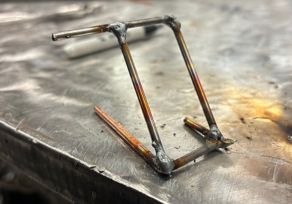
Figure 17
Roll cage rod test piece. This was conducted to test both the strength of the welded rods and the welding prowess of a team member. It had been a while since the team member had welded meaning some practice was necessary. The team threw the piece on the concrete floor multiple times with no failures or bending meaning the roll cage manufacturing technique should lead to a structurally sound roll cage.
Figure 20
Rear bevel gear setup. After printing the differential housings and securing the large bevel gear to the rear axle, the team was finally able to test the fitment of the rear differential. The gears had excellent contact and the
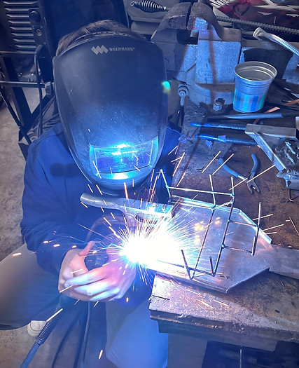
Figure 19
Roll Cage Manufacturing Process. The picture shown is the team welding the first roll cage together. Filling gaps and laying down beads!

Figure 22
Figure 21
Front assembly mock photo without rear axle assembly attached. This photo was taken directly after assembling the front steering and suspension to test fitment and structural rigidity.
Using the Dremel to sand out the rear axle housings in the Hogue machine shop. Plastic shrinkage after 3D printing meant that some sanding was necessary to fit all bearings..

Figure 23
First Drivetrain Test: After wiring the car and assembling the drivetrain for the first time, the team tested the fitment of the gears. The car was able to hit top speed with minimal vibration but observed a loud roar from the rear axle when doing so.
Figure 24
Body roll test video: Video shown was taken on the same day of the drivetrain test. The car was moving under it's own power while the team observed the body roll and handling of the vehicle.

Figure 25
Finalized Roll Cage Side View: Full welded chassis with front bumper and spare tire mount. The roll cage added a significant amount of weight to the vehicle but the structural integrity of the car is through the roof. The team is very happy with the results!
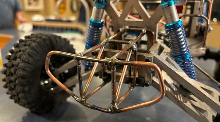
Figure 26
Front Bumper Detail View: The front bumper is made of the same 1/8" steel rod as the rest of the roll cage and features six supporting bars in case of a full frontal collision. An analysis was done on a bumper design that did not feature the diagonal bars and showed that it could handle a 300-pound load. With the additional diagonal bars, the critical load should be much larger than 300-pounds.

Figure 27
Fully Constructed Vehicle: The photo shown is the final product of the Winter Quarter and the Construction phase. All parts have been manufactured, assembled, and wired. It's ready to go!
Drawing Tree

Figure 28